
Training on Isolated Power Systems and Line Isolation Monitors
Sentry 5 Testing
Common NFPA Code Violations
Isolated Power Systems – Common Questions & Answers
Training on Isolated Power Systems and Line Isolation Monitors (Training Used for NFPA 99)
What To Do In Case a LIM Alarms During an Operation
Line Isolation Monitors and the NFPA
How to Troubleshoot a Line Isolation Monitor That Is In Alarm
Silencing the LIM Error Code Alarm
Isolated Power Explained

• It says, “The health care facilities shall provide programs of continuing education for its personnel.”
• Section A.10.5.8.1 defines them as, “Personnel includes physicians, nurses, nursing assistants, engineers, and technicians.”
• If your staff is performing your line isolation monitor testing, are you sure it is correct?
• Are they aware of any changes in the NFPA 99?
• Is it being properly documented?
• We will discuss how isolated power is different than power systems
1. History of Isolated Power
2. How Isolated Power System Works
3. What Makes Up an Isolated Power System
• We will explain why the possibility of a physical shock or a spark in an oxygen environment is greatly reduced.
1. When Is Isolated Power Required?
2. When Is Testing of Line Isolation Monitor Required?
3. How to self-Test the Line Isolation Monitors
• We will, also, consider what should you do if the line isolation monitor alarms.
1. How to Determine if the Panel or Equipment Is Defective
2. What to Do in Case of An Alarm
3. Establish a Maintenance Logbook
4. Isolated Power and Line Isolation Monitor - Q&A

1. In 1951, the NFPA required isolated power systems in the operating room. The requirement was to keep the path from each electrical conductor to ground as high of a resistance as possible
a. This would reduce any spark from occurring and causing a fire
b. Reducing electrical shocks to all present in the operating room
2. Therefore, the system would need a Static Ground Detector (first generation) to monitor the path from each electrical conductor to ground. The detector measured the imbalance of each side of the isolated transformer to ground.

Static Ground Detector
3. The idea was spot on, but the technology had a long way to go.
a. The monitoring device was either in “Alarm” or “Safe” mode
b. The NFPA required monthly testing of these devices.
c. In today’s world, where lawsuits are so commonplace, these devices pose a physical safety risk to the patient and staff. The financial and political risks are huge to the hospital
d. It may be hard to believe, but some of these devices are still around
4. In 1971 the second-generation monitor was a Dynamic Ground Detector, but it had flaws:
a. Its monitor hazard leakage was anywhere from 500 to 1,000 ma
b. It used a switching relay to test one line to ground then switched over, and tested the second line to ground
c. At times, this caused interference with other equipment, like heart monitors
5. Then came the third generation of line isolation monitors (LIM).
a. They could now be in different packages - self contain unit, bulkhead style, etc.
b. The trip point would be either 2 ma or 5 ma type
c. These LIMs continually measure the resistive and capacitive paths from each conductor to ground without switching
6. The 1996 Edition of NFPA 99 changed the code to allow a self-testing, self-calibrating LIM
7. Today, we have the most robust line isolation monitor ever developed, the Sentry 5. Designed and manufactured for Isolated Power Specialist who is the sole distributor of the Sentry 5 line isolation monitor.

8. The following are advantages of the new Sentry 5 line isolation monitor:
a. Testing requirements by the hospital are after installation and every 12 months
i. Testing of analog type of LIMs requires testing by the hospital once a month
b. Therefore, this new LIM saves the hospital money and time
9. Over the years, the use of isolated power systems IPS) have changed from when all evasive procedure rooms had IPS to where only wet procedure location shall have it today (the only exception is the state of North Carolina)
10. NFPA 99 2012 Edition 6.3.2.2.8.4 states: “Operating rooms shall be considered to be a wet procedure location, unless a risk assessment conducted by the health care governing body determines otherwise.”
11. It also says at Annex A.6.3.2.2.8.4: “In conducting a risk assessment, the health care governing body should consult with all relevant parties, including, but not limited to, clinicians, biomedical engineering staff, and facility safety engineering staff.”
II. How Isolated Power Systems Work
1. Many hospitals; however, see the benefits of having and maintaining IPSs in all operating rooms even though the room may not start out as a wet procedure location, they still have frequent spillage of fluids and an oxygen enriched area.
2. Some of the advantages of isolated power systems are:
a. Reduced shock hazard and fires
b. Maintains continuity of power even when the equipment power may short one line to ground. For the breaker to trip both lines must short together, short to ground at same time or draw too much current for what the breaker is listed.
c. Something for nothing – noise reduction
d. Advanced warning of equipment failure
3. Today, there is more dependency on electrical apparatus for the preservation of lives of hospitalized patients.
a. Patient’s life may depend on artificial circulation of the blood
b. In other operations, life sustaining electric impulses that stimulate and regulate heart action
c. Doctors or nurses may be standing in prepping solution, blood, urine and other conductive fluids that reduce resistance to ground and increase the possibility of an electrical shock

Diagram 1
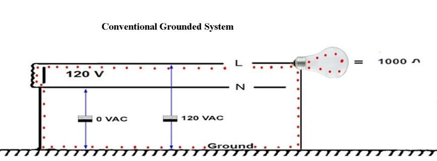
Diagram 2
2. Diagrams 1 and 2 show the schematic of a conventional grounded system. The neutral of the transformer is bonded to ground (green line), which, if adequately sized, will provide equipotential bond between the neutral and ground conductors. As the diagrams show, normally we would expect 0 Volts from ground to neutral and 120 Volts from the line conductor to either ground or neutral.
3. If we assume that a person has a body resistance of 1,000 Ohms, and comes into contact with the live conductor, we can expect the result, as shown in the equivalent circuit below.


Diagram 3
4. A current of 120 mA would flow from the line conductor – via the 1,000 Ohm person – and return to the neutral via the very low impedance neutral-ground connection. This 120 mA could prove extremely dangerous for our 1,000 Ohm person (diagram 3).
5. Should our person have a reduced ohmic resistance, due to excessive moisture or internal body composition, we could expect potentially lethal current to flow.
III. What Makes Up an Isolated Power System
1. Isolation Transformer – Primary windings are not reference to secondary windings nor are the secondary windings referenced to ground.
a. NFPA 99 3.3.90: says “A transformer of the multiple winding type, with the primary and secondary windings physically separated, that the inductively couples its ungrounded secondary winding to the grounded feeder system that energizes its primary winding,” (Diagram 4)
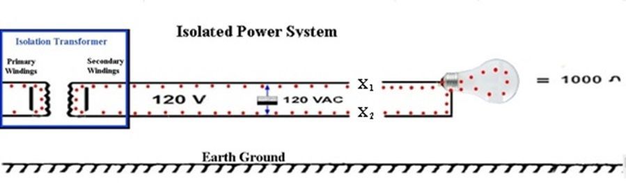
Diagram 4
2. Line Isolation Monitor (LIM) – NFPA 99 - 3.3.97 says “A test instrument designed to continually check the balance and unbalanced impedance from each line of an isolated circuit to ground and equipped with a built-in test circuit to exercise the alarm without adding to the leakage current hazard.” (Diagram 5)
3.

Diagram 5
4. Reference Ground Point – NFPA 99 – 3.3.155: says “The ground bus of the panelboard or isolated power system panel supplying the patient care area.” This is earth ground. All equipment receptacles reference to this point and new operating rooms must be within .1 Ohm or less to this reference ground. NFPA 99 6.3.3.1.6.2
5. Circuit Breaker Panelboard – UL Listed Panel for Hospital Application on Isolated Power can be up to 16 each 2 pole circuit breakers. All breakers on the secondary side of transformer must be 2 pole for single phase power and 3 pole for three phase systems.
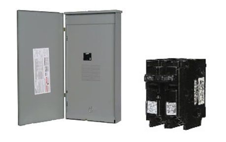
6. Systems can have other devices such as ground jacks, receptacles, etc. built into the panels (see Catalogs).

IV. When Is Isolated Power Required?
1. The NFPA 99 2012 Edition 6.3.2.2.8.1 stipulates: “Wet procedure locations shall be provided with special protection against electric shock.”
a. NFPA 99 6.3.2.2.8.2 says that this special protection shall be provided by isolated power without interrupting the power or GFCI if interruption of power can be tolerated. If interruption of power can not be tolerated you must have isolated power. Note that GFCI receptacles will not work on isolated power and must be on grounded power.
2. For electrical safety, the Health Care Facilities Code recommends isolated power systems whenever a power outage is unacceptable during a ground fault condition.
a. NFPA 99 2012 Edition 6.3.2.2.8.4 states: “Operating rooms shall be considered to be a wet procedure location, unless a risk assessment conducted by the health care governing body determines otherwise.”
3. However, the governing body of any facility can decide to have isolated power installed where they feel extra precaution warrants a reduction in the possibility of a power outage, shock, or fire.
V. Testing Requirements for Line Isolation Monitors
1. As we previously discussed, the Sentry 5 LIM is the state-of-the-art line isolation monitor. The Sentry 5 has automated self-test and self-calibration capabilities the NFPA requires the testing to be every 12 months instead of monthly.
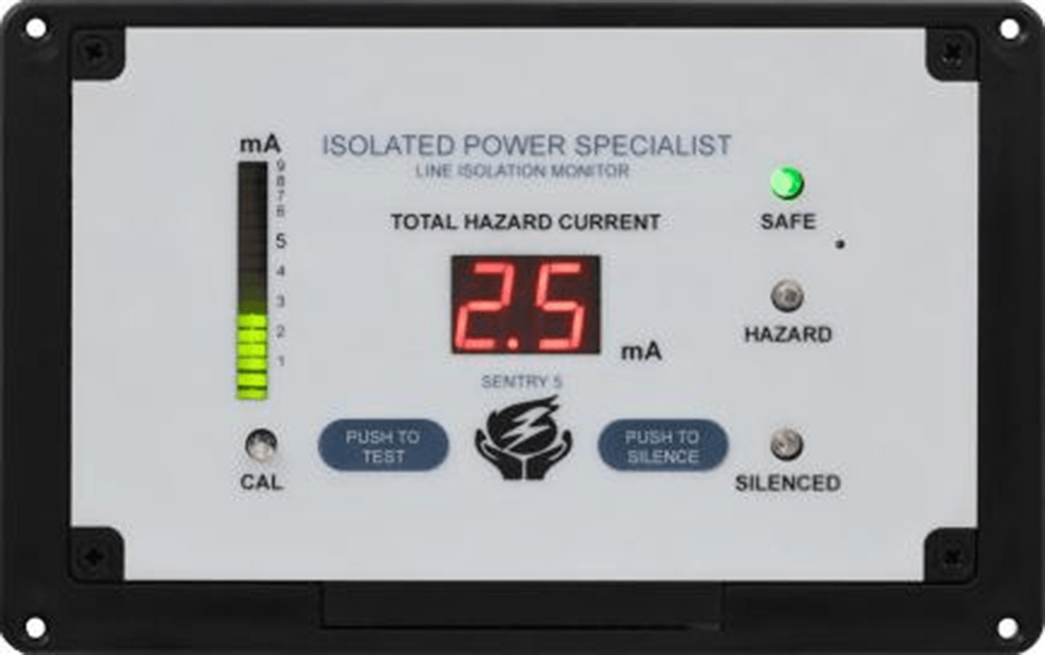
Sentry 5
2. Certain types of LIMs require monthly testing. It depends on the type of LIM (analog LIM that do not test themselves daily etc.).
1. 6.3.4.1.4 The LIM circuit shall be tested at intervals of not more than 1 month by actuating the LIM test switch (see 6.3.2.6.3.6). For a LIM circuit with automated self-test and self-calibration capabilities, this test shall be performed at intervals of not more than 12 months. Actuation of the test switch shall activate both visual and audible alarm indicators.
3. When to test line isolation monitors with an external fault load:
a. After “installation and prior to being placed in service”
1. 6.3.3.3.2 Line Isolation Monitor Tests. The line isolation monitor (LIM) circuit shall be tested after installation, and prior to being placed in service, by successively grounding each line of the energized distribution system through a resistor whose value is 200 × V (ohms), where V equals measured line voltage. The visual and audible alarms (see 6.3.2.6.3.2) shall be activated.
b. 6.3.4.1.5 After repair or renovation to the electrical distribution system, the LIM circuit shall be tested in accordance with 6.3.3.3.2
VI. How to Self-Test the Line Isolation Monitors
1. The Sentry 5 line isolation monitor will automatically perform a self-test when it is powered up.
2. If the Sentry 5 loses power and then regains it again, the Sentry 5 will see this as a power up situation and perform a self-test.
3. To manually initiate a self-test, simply press the “Push To Test” button.

a. The Sentry 5 will perform several internal tests including the required audible and visual tests.
b. The Sentry 5 is set to alarm at 4.8 ma; therefore, the line isolation monitor will simulate an internal load until the LIM reaches 4.8ma.
VII. How to Determine If a Panel or Equipment Is Defective?
1. Determining what is causing the alarm can be difficult.
a. Where is the alarm being generated from (the panel, a circuit in the panel, malfunctioning LIM, etc.)?
b. What is causing the alarm (frayed wiring, defective transformer, wires in liquid, etc.)
2. A blog on our website documents a step-by-step approach to solving this problem. Go to isolated-power.com / Categories / Technology / How to Troubleshoot a Line Isolation Monitor Alarm
3. If the documentation, mentioned in the previous step, does not resolve the problem, feel free to call Isolated Power Specialist at 859-640-2959.
VIII. What to Do in Case of An Alarm
1. An alarm will occur in one of two conditions:
a. During an operation
b. No operation in progress
2. Naturally, the situations are very different and, so are the actions needed
3. Posted on our website is the documentation for both situations. Go to isolated-power.com / Categories / Technology / What To Do In Case a LIM Alarms During an Operation
IX. Establish A Maintenance Logbook
1. The NFPA requires that all facilities with wet procedure locations maintain accurate records. In Section 6.3.4.2 under the heading of “Record Keeping” states the following:
• 6.3.4.2.1.1 A record shall be maintained of the tests required by this chapter and associated repairs or modification.
• 6.3.4.2.1.2 At a minimum, the record shall contain the date, the rooms or areas tested, and an indication of which items have met, or have failed to meet, the performance requirements of this chapter.
• 6.3.4.2.2 Isolated Power System (Where Installed). A permanent record shall be kept of the results of each of the tests.
2. An advantage to having Isolated Power Specialist perform the testing and repairs of all line isolation monitors is the maintaining of this logbook. Although it resides at your site, the entries satisfy the NFPA’s requirements. Test reports and letter of certification will be given to hospital to put in the Maintenance Log Book. Also we can test all manufactures LIMs and replace if found during the annual testing, saving an extra trip and down time to replace defective LIMs.
X. Questions or Comments
1. If you have questions or comments, please submit them at the bottom of the website page isolated-power.com / Contact Us.
